Installation
Well. this shouldn’t be our duty as those are 3rd party sensors, but as it is a common request, these are the general rules:
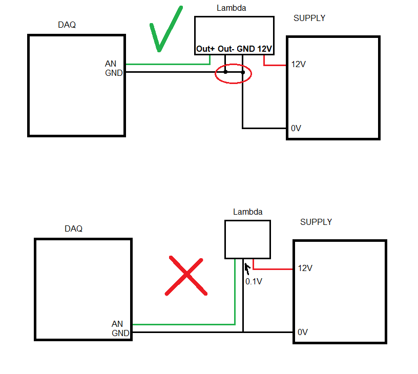
- Some lambdas (Innovate and UEGO) have a “output-” which must be connected to GND at the controller side (not the DAQ side), check the first picture.
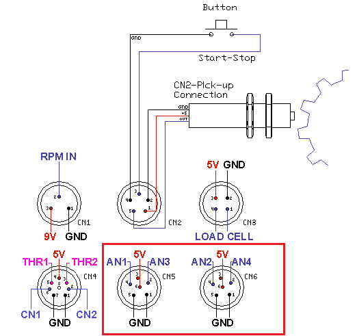
- Connect output+ and output- to pin4 and pin 5 of the 6-pin connectors to DAQ: SP1, SP1+, SP3, SP5 (for Lambda 1 or Lambda 2 depending on the connector) (second picture). For SP4 and SP6 there are specific screw-connectors with the AN1 and AN2 labels.
- Power: of course it is always external, you can use a battery or a 12V power supply
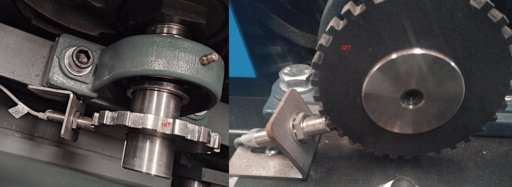
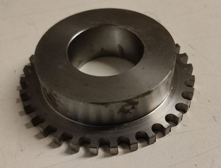
All dyno DAQ kits include one or more gear tooth (16T) by default. The geartooth is not machined, it has a small hole to work as a center.
Typically the gear has to be machined to the axle size (for a motorcycle dyno normal sizes are 50-55 mm, but it can be any), and installed with a holding screw.
Alternatively we can ship machined gears, but they have an extra cost (85€ at 15/DEC/2025). Of course the size must be specified before placing the order
Calibration of loadcell, for dyno running with SportDevices SP1+, SP3, SP4, SP5 and SP6 DAQ units.
Procedure may be different depending on how the dyno is constructed. In this description there is use “calibration bar” and “Calibration weight”.
The purpose of calibrating the load cell is because the load cell normally is the most important factor in HP / TQ calculations in most dyno software.
Brake Torque is converted to linear force into the load cell thanks to balljoints and the physical position of the cell with respect the brake axle (load cell lever). This force is
converted to real-time data. Therefore, it is extremely important to perform this part of the dyno calibration 100% correctly.
An incorrectly calibrated loadcell will give incorrect dyno readings !!
It is recommended to do calibration, on a regular basis. As part of normal service on your dyno.
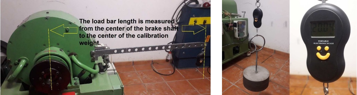
The load bar length is measured from the center of the brake shaft to the center of the calibration weight. The location of the loadcell has no significance with this method. The
software will automatically calculate the correct calibration factor.
A calibration weight is an important tool, and should therefore be stored and treated as an every important measuring tool.
The weight you should choose must be based on what max weight the load cell is nominated for and the length of the bar.
The purpose is to apply so much of the max load to the load cell, to get a better calibration.
Step 1:
Open Loadcell Wizard and mount your cabling bar (Without weight on the bar).
The weight of the bar does not matter at this time. And will be offset at the end of calibration.
Zeroing:
- SP1+, SP5, SP6: The “zero setting” shouldn’t be used with these DAQs. Nevertheless, it is necessary to (re)Start the DAQ to execute the zeroing process cancels the bar’s weight
- SP3 and SP4: As those (old) DAQs do not perform the internal zeroing at startup, thus it is necessary to use the “Set to Zero” button.
Step 2:
Enter the Cabling bar length value (say 270 mm) and the calibration weight value (say 20 kg)
The next step is to place your calibrating weight on the bar. And then press “Calibration”
After the calibration the calibration weight and bar must be removed and the zero performed again:
- SP1+, SP5, SP6: restart the DAQ so the new (negative) offset is cancelled.
- SP3 and SP4: go back to “Step 1” and press “Set to Zero” again. This makes the offset for the calibration bar weight.
Go back to Step 2 and press “Ok”, calibration is now complete and stored on your computer
Alternative Calibration Methods (Depends on the dyno)
Some dynamometers can have a dedicated place at the same position that the load cell to perform the calibration directly over the cell. In these cases, the calibration bar length is the same than the load cell lever. If load cell lever (distance from axle to cell is 300 mm, calibration bar = 300 mm)
These methods have the advantage that do not use a physical calibration bar that adds a weight when installed in the brake (and subtract a weight offset when removed from the brake)
P.I.D. coefficients determine the brake response to the difference between the desired speed (target) and the current speed (this difference is called error).
The DAQ (SP1+ / SP5 / SP6) implements a standard PID, with I constant proportionally to P (Kp) Ti, this allows changing only Kp constant and SP5 will modify Ki to keep the same dynamic behavior. (Ki = Kp * 1 / Ti)
The DAQ does not implement a Kd derivative constant, but it implements a more sophisticated overshoot control.
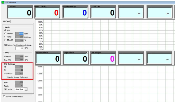
A good starting point for PID setup is:
Kp = 1-40 (1 to 5 for engine, hub and motorcycle dynos, 5 to 10 for car dynos with small rollers, and up to 40 for big rollers)
Ti = 1 (0.5 to 1.0)
TD = 0
- Kp basically controls the reaction time. Control can be made faster increasing Kp, but excessively high values will cause fast oscillations on the system, thus a balance has to be found between speed response and stability.
Kp by itself cannot make the speed control to reach the exact target speed, for this reason the integral control (I) is used. - Ti is (normally) modified in a narrow interval (typically 0.5 to 1.5). A low Ti will provide a faster approaching / drift to the target, specially in steady mode. But a low Ti will decrease the reaction speed (specially for ramp mode)
- Td: is a setting which tries to damp the reaction of the dyno .Normally with roller dynos inertia is high enough and Td is not used. Only lightweight dynos may need the Td setting., but up to cerain level (in steps 0f 0.01) in which the reaction starts to increase the high speed oscillations.
- Accel Filter: when using the Td setting set the “accel filter” to 1 to improve the calculation of the acceleration internal channel
Note: Since the addition of current-closed-loop to the Brake Power Supplies (PWS1.5, PWS3.x, HS-PWS) the reaction time of the system has been improved a lot.
Each power supply comes with 3 inputs: PWM (2 pins), CAN (4 pins) and Analog / Potentiometer (3 pins). In general only one can be used at a time for the speed control (PWM or CAN), with the exception of a safety potentiometer or brake pedal that can work in parallel as a safety control (only when it is necessary a rough braking)
Note that SP1+ and old SP4 have only PWM output, while SP5 and SP6 have also a CAN bus.
Advantages of PWM (for one or two brakes):
- There is a direct relationship between the DAQ output with the function in the Power Supply. Front rolller connector will always output the PWM for front Brake, and Rear Roller Connector will always output the PWM for rear Brake. No possible confusion (if cables are traced)
- It is not affected by interferences or collision between several modules. Each PWM line is only point to point
Disadvantages of PWM / advantages of CAN
- There is no feedback in PWM. CAN is more useful for 2-HUB, AWD and 4-HUB dynos as the SW can receive the feedback of each power supply before starting the test, and can record all telemetry (current and temperature) of each power supply to be stored with the tests as potential diagnosis in case something is wrong
- CAN allows to perform a Brake Resistance Measurement from the software
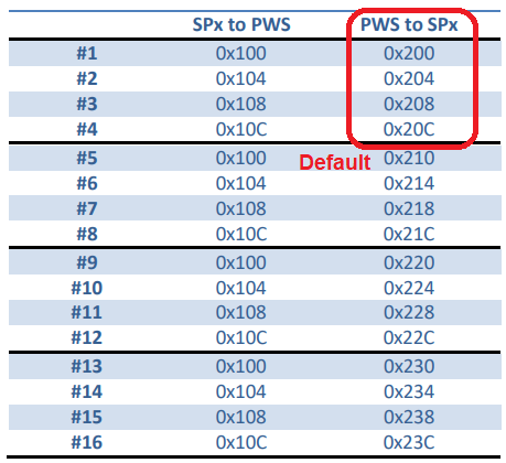
- PWM can have problems if many PWS have to be connected in parallel as the optocouplers take some power of the PWM line, while PWS provide a protocol for CAN to have the same CAN ID (for receiving commands) and different ID for telemetry. In this way a SP6 could control up to 16 x PWS, max 4 per channel
Connection:

- PWM: SP1+, SP5 and SP6 include the PWM line in the 4th pin of the 5-pin connector (roller connector). Each Power Supply include a “Y” cable that splits this line and GND for the PWM, and provides another 5-pin connector for the hall sensor cable. Note that in the hall sensor+switch cable the pin 4 is used as GND (mainly for SP1), this is only possible when connecting the hall sensor + ext. cable to the output of the “Y” cable, not directly to the SP1+/SP5/SP6 output
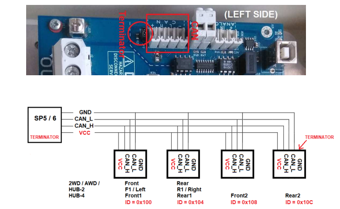
- CAN: SP5 and SP6 provide a round 8-pin connector (GX-16) with CANH and CANL lines, and also GND and 5V (note that from PWS3.3 5V is no longer necessary from the DAQ, as it is obtained through a DC/DC in the same PWS). When more than one PWS is going to be used, the 4-pin connector in the PWS has to be chained to reach all of them
Terminators:
SP5 and SP6 include a terminator inside the PCB. Also, the last PWS in the chain must have the terminator jumper SET while the intermediate PWS will have them disabled.
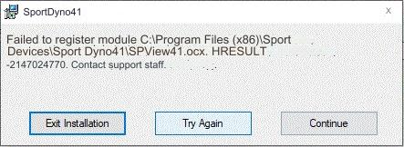
MSCOMCTL.OCX and SPView41.OCX errors
A few customers reported errors when installing the Software at the point when the installer is registring some OCX controls. For instance the MSCOMCTL.OCX there are two versions, in old Sportdyno V3.5 we used the version (6.01.9782) where in current Sportdyno versions we use a more recent version (6.01.9846) and for some reason this causes issues in some computers. A similar error can be shown when registring the SPVIEW41.OCX control
A temporary fix for this error, until we discover why some (few) computers show this error, is just installing the old Sportdyno V3.5 and then installing the latest Sportdyno V4.1.x versions, then the installation is successfull
Something that causes many misunderstandings to new users regarding the SP1 configuration is the confguration of number of teeth and prescaler due to the fact that the SP1 does not syncrhonize these settings with the PC (the SP1 will not send this information during the connection process and then the PC will not be able to synchronize it). Then it is necessary:
- Ensure that the connection between the PC and the SP1 is established before configure these settings
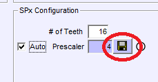
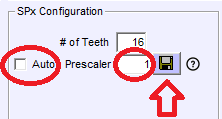
- Configure the Number of Teeth and prescaler. For our stock gear it is Teeth=16 and Prescaler=1 (in most cases). Note that this configuration is only valid for rollers over 320 mm and max speed below 225 km/h! (max roller speed 3750 rpm). For higher speeds use the “auto” setting, which will set the prescaler to 4 to avoid problems. Please check the table below
- Press the “disquette” button, or press OK and reply “YES” to the question “do you want to send the new settings?”
- Verify that the SP1 LCD shows the stored value (this lasts only 2 or 3 seconds)
** Note: we are testing a new firmware which implements the same synchronization as SP1+, SP5 and SP6. This FW could be used in all SP1 V4 units
AUTOMATIC Prescaler Selection:
When the “auto” setting is ON, the software will select
- Teeth: 1 to 12: prescaler = 1
- Teeth: 13 to 49: prescaler = 4 (note that for our stock 16T gear it will chose prescaler=4, which can reduce the accuracy at low speeds)
- Teeth: 50 or more: prescaler = 16
Manual Prescaler Selection
In general when SP1 is used with our stock 16T gear, number of Teeth = 16 and prescaler = 1, but only for rollers over 320 mm diameter and top speed below 225 km/h. For lower diameters or higher speeds prescaler should be 4
As maximum SP1 input is 1000 pulses per second, the user should ensure that the top frequency is not overpassed using the following formula:
Max Freq = Max Roller RPM / 60 * Teeth / prescaler
(Max Roller RPM = Max Speed (km/h) / 3.6 / (diameter_mm / 1000) * 3.1416) * 60)
Example:
For instance for a 320 mm roller running Max Roller RPM at 225 km/h is: Max Roller RPM = 225 / 3.6 / (0.320 * 3.1416) * 60 = 3730 RPM
And for 16T and prescaler = 1 Max Freq = 3730 / 60 * 16 / 1 = 994 Hz
Then for higher speeds (over 225 kmh) or lower roller diameters (below 320 mm) the prescaler should be 4 as in the automatic mode.
For the rest of combinations, say teeth 80 normally there is no need to do any calculation. The 16T is a little more problematic because it is in the border between prescaler=1 and prescaler=4, but it was selected as stock gear because it provides more pulses for the braked dynamometers.
Common Issues
Something that causes many misunderstandings to new users regarding the SP1 configuration is the confguration of number of teeth and prescaler due to the fact that the SP1 does not syncrhonize these settings with the PC (the SP1 will not send this information during the connection process and then the PC will not be able to synchronize it). Then it is necessary:
- Ensure that the connection between the PC and the SP1 is established before configure these settings
- Configure the Number of Teeth and prescaler. For our stock gear it is Teeth=16 and Prescaler=1 (in most cases). Note that this configuration is only valid for rollers over 320 mm and max speed below 225 km/h! (max roller speed 3750 rpm). For higher speeds use the “auto” setting, which will set the prescaler to 4 to avoid problems. Please check the table below
- Press the “disquette” button, or press OK and reply “YES” to the question “do you want to send the new settings?”
- Verify that the SP1 LCD shows the stored value (this lasts only 2 or 3 seconds)
** Note: we are testing a new firmware which implements the same synchronization as SP1+, SP5 and SP6. This FW could be used in all SP1 V4 units
AUTOMATIC Prescaler Selection:
When the “auto” setting is ON, the software will select
- Teeth: 1 to 12: prescaler = 1
- Teeth: 13 to 49: prescaler = 4 (note that for our stock 16T gear it will chose prescaler=4, which can reduce the accuracy at low speeds)
- Teeth: 50 or more: prescaler = 16
Manual Prescaler Selection
In general when SP1 is used with our stock 16T gear, number of Teeth = 16 and prescaler = 1, but only for rollers over 320 mm diameter and top speed below 225 km/h. For lower diameters or higher speeds prescaler should be 4
As maximum SP1 input is 1000 pulses per second, the user should ensure that the top frequency is not overpassed using the following formula:
Max Freq = Max Roller RPM / 60 * Teeth / prescaler
(Max Roller RPM = Max Speed (km/h) / 3.6 / (diameter_mm / 1000) * 3.1416) * 60)
Example:
For instance for a 320 mm roller running Max Roller RPM at 225 km/h is: Max Roller RPM = 225 / 3.6 / (0.320 * 3.1416) * 60 = 3730 RPM
And for 16T and prescaler = 1 Max Freq = 3730 / 60 * 16 / 1 = 994 Hz
Then for higher speeds (over 225 kmh) or lower roller diameters (below 320 mm) the prescaler should be 4 as in the automatic mode.
For the rest of combinations, say teeth 80 normally there is no need to do any calculation. The 16T is a little more problematic because it is in the border between prescaler=1 and prescaler=4, but it was selected as stock gear because it provides more pulses for the braked dynamometers.