Category:
Installation
Each power supply comes with 3 inputs: PWM (2 pins), CAN (4 pins) and Analog / Potentiometer (3 pins). In general only one can be used at a time for the speed control (PWM or CAN), with the exception of a safety potentiometer or brake pedal that can work in parallel as a safety control (only when it is necessary a rough braking)
Note that SP1+ and old SP4 have only PWM output, while SP5 and SP6 have also a CAN bus.
Advantages of PWM (for one or two brakes):
- There is a direct relationship between the DAQ output with the function in the Power Supply. Front rolller connector will always output the PWM for front Brake, and Rear Roller Connector will always output the PWM for rear Brake. No possible confusion (if cables are traced)
- It is not affected by interferences or collision between several modules. Each PWM line is only point to point
Disadvantages of PWM / advantages of CAN
- There is no feedback in PWM. CAN is more useful for 2-HUB, AWD and 4-HUB dynos as the SW can receive the feedback of each power supply before starting the test, and can record all telemetry (current and temperature) of each power supply to be stored with the tests as potential diagnosis in case something is wrong
- CAN allows to perform a Brake Resistance Measurement from the software
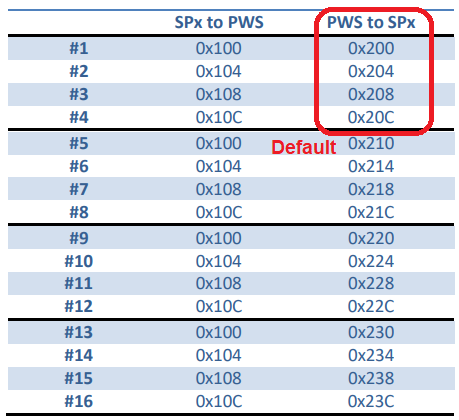
- PWM can have problems if many PWS have to be connected in parallel as the optocouplers take some power of the PWM line, while PWS provide a protocol for CAN to have the same CAN ID (for receiving commands) and different ID for telemetry. In this way a SP6 could control up to 16 x PWS, max 4 per channel
Connection:

- PWM: SP1+, SP5 and SP6 include the PWM line in the 4th pin of the 5-pin connector (roller connector). Each Power Supply include a “Y” cable that splits this line and GND for the PWM, and provides another 5-pin connector for the hall sensor cable. Note that in the hall sensor+switch cable the pin 4 is used as GND (mainly for SP1), this is only possible when connecting the hall sensor + ext. cable to the output of the “Y” cable, not directly to the SP1+/SP5/SP6 output
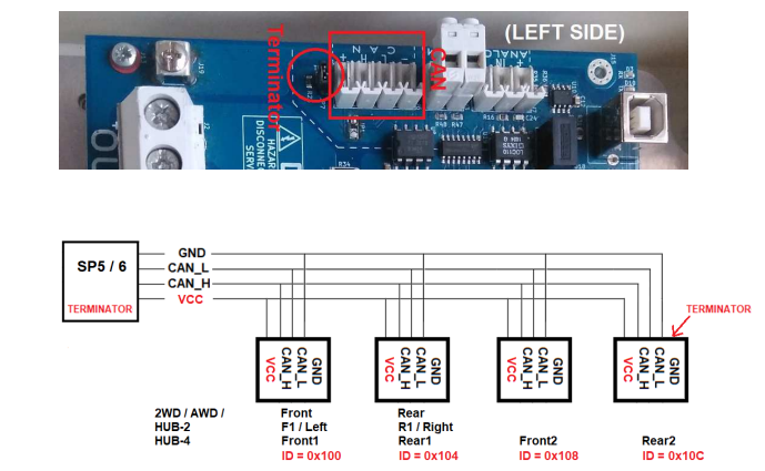
- CAN: SP5 and SP6 provide a round 8-pin connector (GX-16) with CANH and CANL lines, and also GND and 5V (note that from PWS3.3 5V is no longer necessary from the DAQ, as it is obtained through a DC/DC in the same PWS). When more than one PWS is going to be used, the 4-pin connector in the PWS has to be chained to reach all of them
Terminators:
SP5 and SP6 include a terminator inside the PCB. Also, the last PWS in the chain must have the terminator jumper SET while the intermediate PWS will have them disabled.