P.I.D. coefficients determine the brake response to the difference between the desired speed (target) and the current speed (this difference is called error).
The DAQ (SP1+ / SP5 / SP6) implements a standard PID, with I constant proportionally to P (Kp) Ti, this allows changing only Kp constant and SP5 will modify Ki to keep the same dynamic behavior. (Ki = Kp * 1 / Ti)
The DAQ does not implement a Kd derivative constant, but it implements a more sophisticated overshoot control.
A good starting point for PID setup is:
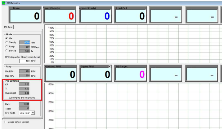
Kp = 1-40 (1 to 5 for engine, hub and motorcycle dynos, 5 to 10 for car dynos with small rollers, and up to 40 for big rollers)
Ti = 1 (0.5 to 1.0)
TD = 0
- Kp basically controls the reaction time. Control can be made faster increasing Kp, but excessively high values will cause fast oscillations on the system, thus a balance has to be found between speed response and stability.
Kp by itself cannot make the speed control to reach the exact target speed, for this reason the integral control (I) is used. - Ti is (normally) modified in a narrow interval (typically 0.5 to 1.5). A low Ti will provide a faster approaching / drift to the target, specially in steady mode. But a low Ti will decrease the reaction speed (specially for ramp mode)
- Td: is a setting which tries to damp the reaction of the dyno .Normally with roller dynos inertia is high enough and Td is not used. Only lightweight dynos may need the Td setting., but up to cerain level (in steps 0f 0.01) in which the reaction starts to increase the high speed oscillations.
- Accel Filter: when using the Td setting set the “accel filter” to 1 to improve the calculation of the acceleration internal channel
Note: Since the addition of current-closed-loop to the Brake Power Supplies (PWS1.5, PWS3.x, HS-PWS) the reaction time of the system has been improved a lot.