Installation
Something that causes many misunderstandings to new users regarding the SP1 configuration is the confguration of number of teeth and prescaler due to the fact that the SP1 does not syncrhonize these settings with the PC (the SP1 will not send this information during the connection process and then the PC will not be able to synchronize it). Then it is necessary:
- Ensure that the connection between the PC and the SP1 is established before configure these settings
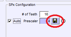
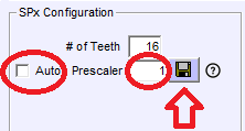
- Configure the Number of Teeth and prescaler. For our stock gear it is Teeth=16 and Prescaler=1 (in most cases). Note that this configuration is only valid for rollers over 320 mm and max speed below 225 km/h! (max roller speed 3750 rpm). For higher speeds use the “auto” setting, which will set the prescaler to 4 to avoid problems. Please check the table below
- Press the “disquette” button, or press OK and reply “YES” to the question “do you want to send the new settings?”
- Verify that the SP1 LCD shows the stored value (this lasts only 2 or 3 seconds)
** Note: we are testing a new firmware which implements the same synchronization as SP1+, SP5 and SP6. This FW could be used in all SP1 V4 units
AUTOMATIC Prescaler Selection:
When the “auto” setting is ON, the software will select
- Teeth: 1 to 12: prescaler = 1
- Teeth: 13 to 49: prescaler = 4 (note that for our stock 16T gear it will chose prescaler=4, which can reduce the accuracy at low speeds)
- Teeth: 50 or more: prescaler = 16
Manual Prescaler Selection
In general when SP1 is used with our stock 16T gear, number of Teeth = 16 and prescaler = 1, but only for rollers over 320 mm diameter and top speed below 225 km/h. For lower diameters or higher speeds prescaler should be 4
As maximum SP1 input is 1000 pulses per second, the user should ensure that the top frequency is not overpassed using the following formula:
Max Freq = Max Roller RPM / 60 * Teeth / prescaler
(Max Roller RPM = Max Speed (km/h) / 3.6 / (diameter_mm / 1000) * 3.1416) * 60)
Example:
For instance for a 320 mm roller running Max Roller RPM at 225 km/h is: Max Roller RPM = 225 / 3.6 / (0.320 * 3.1416) * 60 = 3730 RPM
And for 16T and prescaler = 1 Max Freq = 3730 / 60 * 16 / 1 = 994 Hz
Then for higher speeds (over 225 kmh) or lower roller diameters (below 320 mm) the prescaler should be 4 as in the automatic mode.
For the rest of combinations, say teeth 80 normally there is no need to do any calculation. The 16T is a little more problematic because it is in the border between prescaler=1 and prescaler=4, but it was selected as stock gear because it provides more pulses for the braked dynamometers.
Common Issues
Windows can eventually detect a high data stream from the DAQ (and previously from the Weather Station) and decide that it is a MOUSE, it will install the Ballpoint Drivers and will block the access from other applications. The cursor in the screen can become crazy as it will interpret the data from the DAQ as mouse movement.
Solution:
- Turn the DAQ OFF, or disconnect the USB from the computer
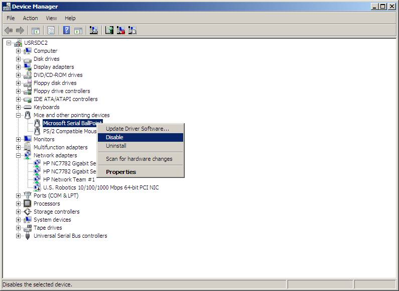
- Manual: Open the Windows Device Manager and DISABLE the Ballpoint device (do not uninstall it, Windows would install it automatically again)
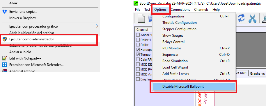
- Automatic: Execute Sportdyno in Admin mode to give the application Admin rights (note that it does not mean to log with an Admin user). Execute the “Options/Disable Ballpoint” menu option. Note: it will only work with Admin rights.
Manual Method:
Automatic Method:
Why sending test files?
Test files include many channels: load cell channels, PID channels (brakes, “calc_rpm”, target RPM, etc), analogue sensors, debug channels, etc. When an issue is reported we NEED to see those channels to know what happened during the run. It is true that some common issues can be seen (more or less) in the final run (for instance when there is a small loop in the power graph it normally happens because the PID settings are not correct), but in general it is much more difficult to see the causes of the issues in the final run than in the test file.
Ple
How sending test files?
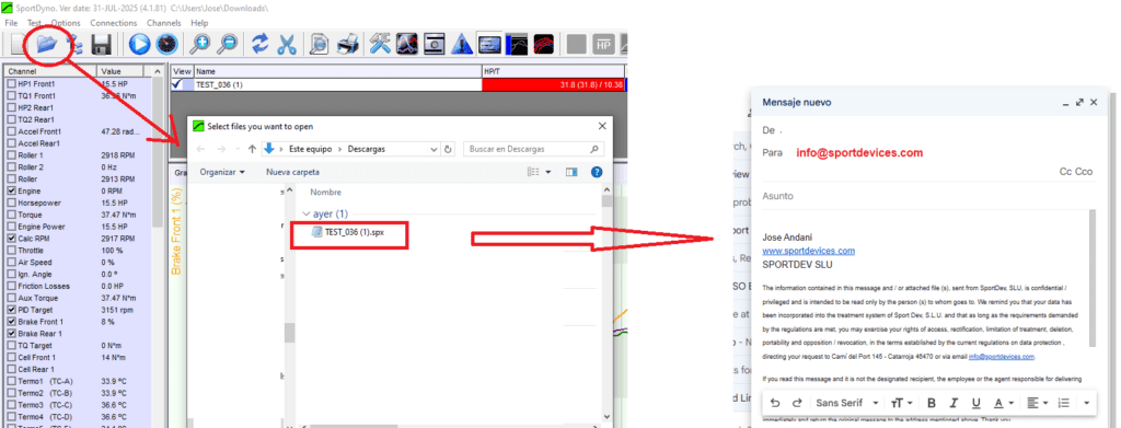
Open – Drag File:
The typical way is just using the Open button to access the existing files and then drag it to an email (or web.whatsapp.com or facebook)
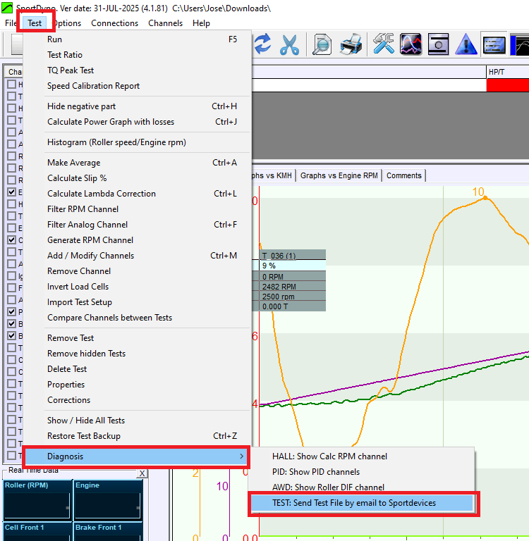
Diagnosis – Send File Menu:
There is a SPECIFIC function for sending files for inspection
Note that for this verification we are using the default “New Lambda (10-18AFR)” type for AN1 / LAMBDA1 channel

Verifying the Heating Up phase
The controller will provide 2 different voltages / outputs for the heating-up and steady phases
- During the first seconds, the controller is in the heating-up phase and will output aprox 2.5V in the output, 14 AFR in the software.
- Once the lambda has reached its working temperature at free air, it will output 5V or 18 AFR (aprox). The sensor should be hot, be careful if touching it
Possible issues:
· The lambda is not physically hot: Check that the voltage provided by the small 12V power supply is stable at 12V with a multimeter (with the controller and the lambda connected).
-
- If the voltage is low then the power supply could be faulty
- If the voltage is 12V normally means that the controller is faulty
- The lambda is hot, but the output stays at 2.5V / 14 AFR, normally this means that the controller is faulty, but check it with another lambda sensor if possible
Verifying the Operating phase
- Apply gas from a lighter (no flame) directly in the lambda sensor orifice, the output should go low fast: 0V / 10 AFR
- Remove the lighter and allow the gas to disipate (or blow the sensor to make it faster), the output should go back to 5V / 18 AFR
Note: if you are having issues with the connection to the DAQ and the software, the voltages can be directly verified in the 6 pin connector from the Lambda Controller at pin 4 (signal) vs pin 5 GND, or at the square plastic connector (check the wires colours in the controller)
During the installation / setup process it is common that some settings are not correct which can lead to ‘absurd’ readings (very high or very low). It is important to do this check list:
- Number of Pulses and Prescaler (a little error in the number of teeth or prescaler usually gives huge errors in the power readings)
- SP1/SP4: please verify the number of teeth and prescaler. Plase read this link: https://sportdevices.com/ufaq/sp1-configuration-inertial-tests ). Also a bad SP1 synchronization can give strange results
- SP1+/SP5/SP6: Software Prescaler is always 1 (except when using High Pulses Encoders and the internal Hardware prescaler, but it is an internal setting)
- Inertia / MOI (a little error here has a little impact in the output)
- Solid roller it is easy to calculate the inertia, please check our spread sheet: http://www.sportdevices.com/download/rollerssheet.xls
- Hollow roller: here the difficulty is to know the internal thickness of the cylinder and the walls. You can check our double-ramp calibration/estimation doc: http://www.sportdevices.com/download/manuals/Double%20Ramp%20Test.pdf
- Load Cell Calibration (when applicable) https://sportdevices.com/ufaq/load-cell-calibration/
- The Test Procedure itself: For Engine Power Measurement it is important to record correctly both phases: acceleration at full throttle and coast down in neutral or clutch pressed (when possible). If the coast down phase has not been recorded it is easy that 20% or more friction losses have not been recorded, then the output will be low
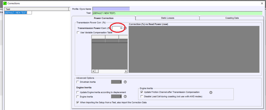
- Power Transmission Correction. In most cases use a value of at least 10% (there are very small engines that need 7%, but most are over 10%). There are other exceptions like electric hub motors (direct traction) and similar which will use correction=0%
After the installation:
It may exist differences specially in high power cars and specially on twin roller dynos
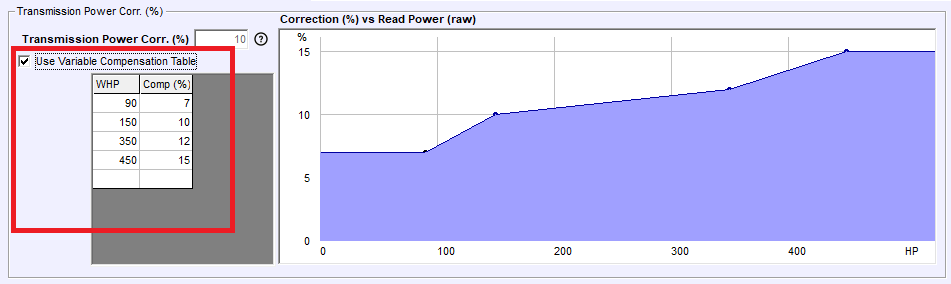
High Power Cars may need a higher ‘power transmission correction’ value, but it is difficult to anticipate it. There is a function that assigns a value from a table, but this table may change change with each car and each dyno
Twin roller dynos are specially complicated with high power cars, even worse if the rollers are more separated. In twin roller dynos there is also another source of differences, which is the tyre deformation: normally the lower the gear the higher the pressure that the tyre does against the front roller and the higher the losses, but these losses cannot be measured in the coast down phase. Then the recommendation is using the higher gear possible in these dynos, and even increase the tyre pressure to reduce the deformation (but if you see that slippage increases then you should reach a balance)
example of tyre deformation
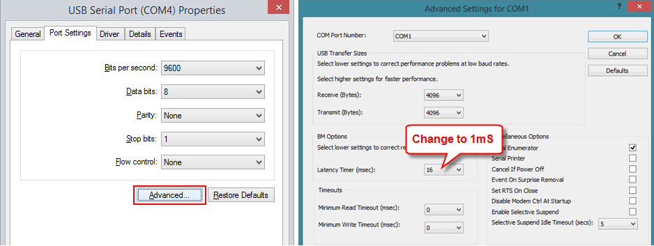
The provided USB-RS232 adapter has a default latency which results too slow for realtime data displaying. It does not affect to the recording but makes the visualization very slow.
There are two options:
- Use the “FTDI (0xnn)” port. When using the FTDI port the software can use the FTDI drive for selecting automatically the latency to 1 ms, which is the easiest way. (see below)
- Configure manually the COM latency to 1 ms (see below). This is recommended only for advanced users.
FTDI Port

Manually setting the COM Latency to 1 ms (advanced)
Something that causes many misunderstandings to new users regarding the SP1 configuration is the confguration of number of teeth and prescaler due to the fact that the SP1 does not syncrhonize these settings with the PC (the SP1 will not send this information during the connection process and then the PC will not be able to synchronize it). Then it is necessary:
- Ensure that the connection between the PC and the SP1 is established before configure these settings
- Configure the Number of Teeth and prescaler. For our stock gear it is Teeth=16 and Prescaler=1 (in most cases). Note that this configuration is only valid for rollers over 320 mm and max speed below 225 km/h! (max roller speed 3750 rpm). For higher speeds use the “auto” setting, which will set the prescaler to 4 to avoid problems. Please check the table below
- Press the “disquette” button, or press OK and reply “YES” to the question “do you want to send the new settings?”
- Verify that the SP1 LCD shows the stored value (this lasts only 2 or 3 seconds)
** Note: we are testing a new firmware which implements the same synchronization as SP1+, SP5 and SP6. This FW could be used in all SP1 V4 units
AUTOMATIC Prescaler Selection:
When the “auto” setting is ON, the software will select
- Teeth: 1 to 12: prescaler = 1
- Teeth: 13 to 49: prescaler = 4 (note that for our stock 16T gear it will chose prescaler=4, which can reduce the accuracy at low speeds)
- Teeth: 50 or more: prescaler = 16
Manual Prescaler Selection
In general when SP1 is used with our stock 16T gear, number of Teeth = 16 and prescaler = 1, but only for rollers over 320 mm diameter and top speed below 225 km/h. For lower diameters or higher speeds prescaler should be 4
As maximum SP1 input is 1000 pulses per second, the user should ensure that the top frequency is not overpassed using the following formula:
Max Freq = Max Roller RPM / 60 * Teeth / prescaler
(Max Roller RPM = Max Speed (km/h) / 3.6 / (diameter_mm / 1000) * 3.1416) * 60)
Example:
For instance for a 320 mm roller running Max Roller RPM at 225 km/h is: Max Roller RPM = 225 / 3.6 / (0.320 * 3.1416) * 60 = 3730 RPM
And for 16T and prescaler = 1 Max Freq = 3730 / 60 * 16 / 1 = 994 Hz
Then for higher speeds (over 225 kmh) or lower roller diameters (below 320 mm) the prescaler should be 4 as in the automatic mode.
For the rest of combinations, say teeth 80 normally there is no need to do any calculation. The 16T is a little more problematic because it is in the border between prescaler=1 and prescaler=4, but it was selected as stock gear because it provides more pulses for the braked dynamometers.
There are two possible causes:
Bad ratio or slip / tyre deformation: Check the actual engine RPM channel or OBDII RPM channel vs Calculated RPM to see if the actual RPM gets far from the calculated RPM graph, specially in the middle section (due to the higher torque)
Excessive filtering: Max recommended filter (LPF: Low Pass Filter) is 1/10 of the test duration (acceleration phase). For instance a test of 8 seconds (acceleration) should use a maximum filter of 0.8s. Tests which use excessive filtering (for instance LPF=4.0 sec) will show the power graph excessive rounded and will show lower HP and TQ results. This can also affect to the top calculated RPM values