Dyno Usage
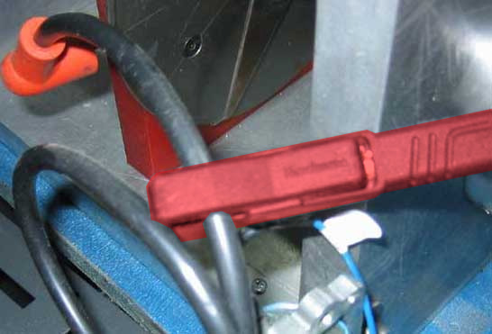
The Capacitive Clamp (Red) (CAP-1) is envisaged to be used mainly on spark cables (High Voltage from coil to the spark). It senses the High Voltage peaks and sends them to the DAQ. In general it is good for single cylinder engines,
Drawbacks: it may get random pulses from other cylinders
There is also a variant (CAP-3) with a blue cable and the 3-pin connector which includes the amplifier circuit in the same clamp, this allows to make the sensing circuit less sensitive and focus only on the near ignition sources, which improves a little its performance on multi cylinder engines. This clamp is provided by default with the SP6 as it only has the 3-pin input
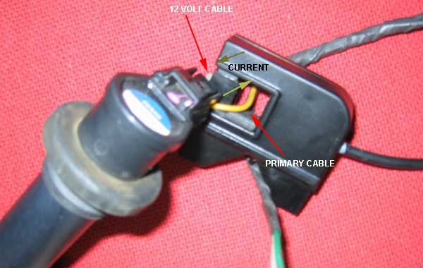
Inductive Clamp (black) (IND-3)
The inductive clamp senses the Current pulses (not voltage) and it is provided mainly to sense the current at ONE of the wires that go to the coil, specially for over-spark coils (as there is no spark cable!).
- In motorcycles typically there are two cables going to the coil, please set the clamp at ONE of the cables. Note that the clamp is sensitive to one direction but less to the other.
- In cars typically we have three cables going to the “amplified coil”, one of the cables is GND, the other is 12V and the other is the low power activation. As it is the coil who amplifies the signal and creates the current pulses, only the GND and 12V cables will have a pulses of current (use the clamp on ONE of them). The signal cable could even have almost Zero current, as normally these coils use an IGBT (its conductivity based on gate’s voltage, not current)
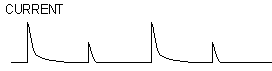
Current model:

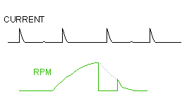
Drawbacks: mnany engines work in a “wasted-spark” schema to simplify the timing (one spark per turn). This means that they do one spark at compression-combustion stroke, but also a spark in exhaust stroke. This spark at exhaust stroke has no impact over the engine performance, but as the pressure is lower than during the combustion the sparks tend to be weaker (it is necessary less voltage to jump the spark gap than when working at a high pressure). This causes that the pulses sensed at the clamp are alternatively high and low, high and low, but also not at a constant level, but the weak pulse may sometimes overpass the activation level, and other times may not. Which will lead to show alternatively the value “RPM”, and “RPM / 2” in the gauges and the graphs
And when the engine decelerates as the amount of air-fuel mixture is very low in the chamber, even the compression phase may show 0 RPM as in the graph below, although this normally happens during a short time as the engine reaches the idling speed quite fast (Neutral Gear or Clutch have to be active to do the coast down test)
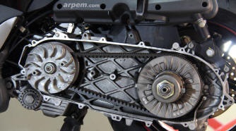
CVTs normally consist of a set of two pulleys that can change their width and a belt that can travel from a closer position in the drive pulley (and a more open position in the driven pulley) which works as a first gear, to a wider position in the drive pulley as the drive pulley becomes compressed (by centrifugal rollers or other mechanisms) which work as a high gear. An important feature of CVTs is that it exists infinite positions between the “low” position to the “high” position, which gives also multiple combinations for the ratio value which change during the test, thus it is NOT possible to perform a standard ratio calibration for CVTs.
There are two ways to test a vehicle with a CVT (Continuous Variable Transmission)
Testing the CVT on its normal way of operation.
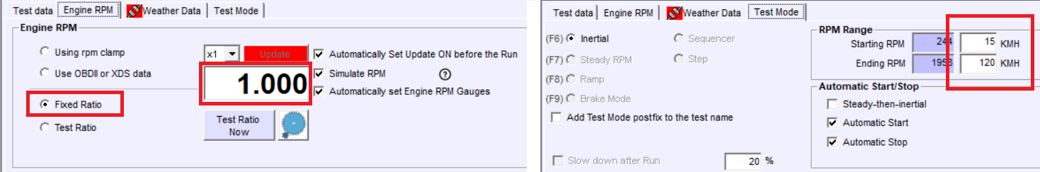
- Set Fixed Ratio = 1.000 (as the ratio changes during the whole acceleration phase) and
- use the starting and ending points referenced to speed. Note that it is also possible to start from a standstill either using manual start or setting the starting speed to 1 km/h
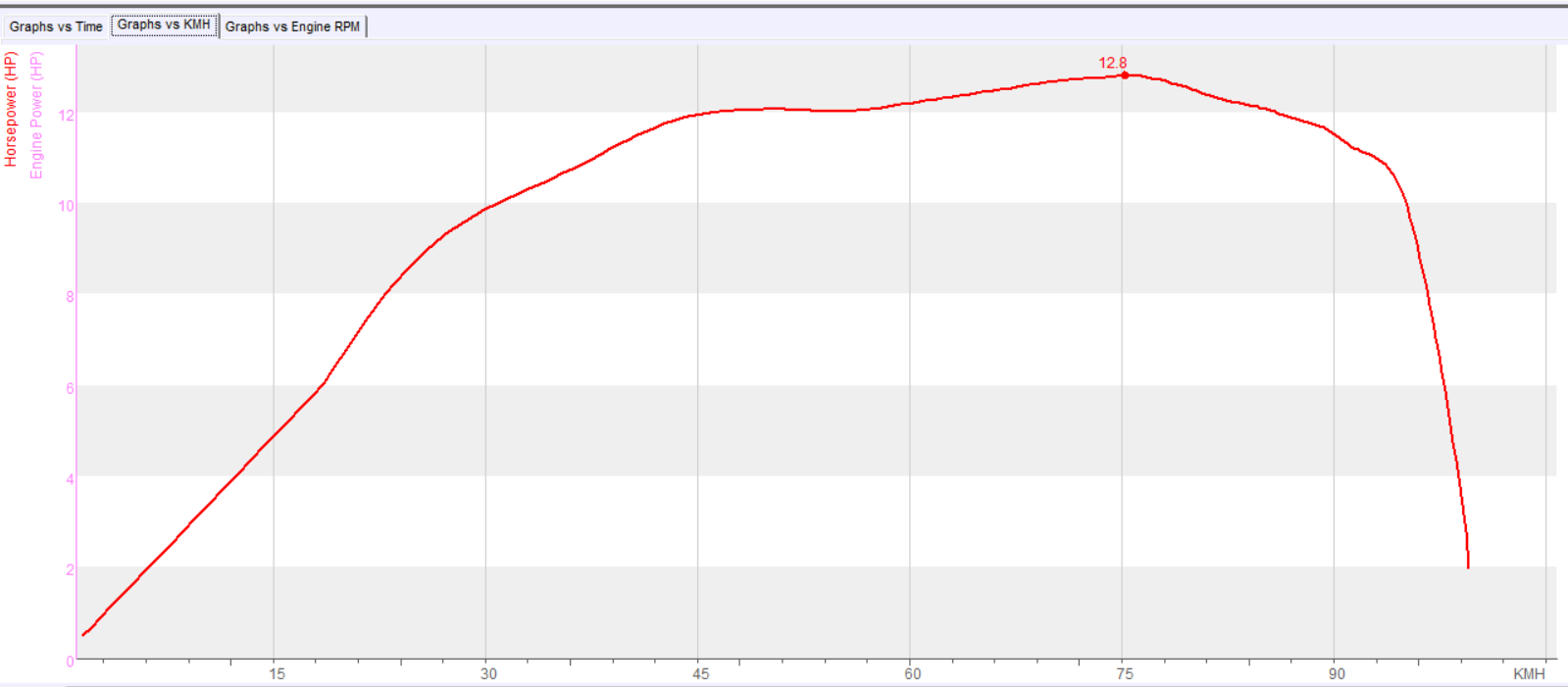
- The resulting test should be displayed as HP (wheel) vs Speed.
- Aux Torque can be used to get the Linear Force (thrust), but not ETQ
- Remarks:
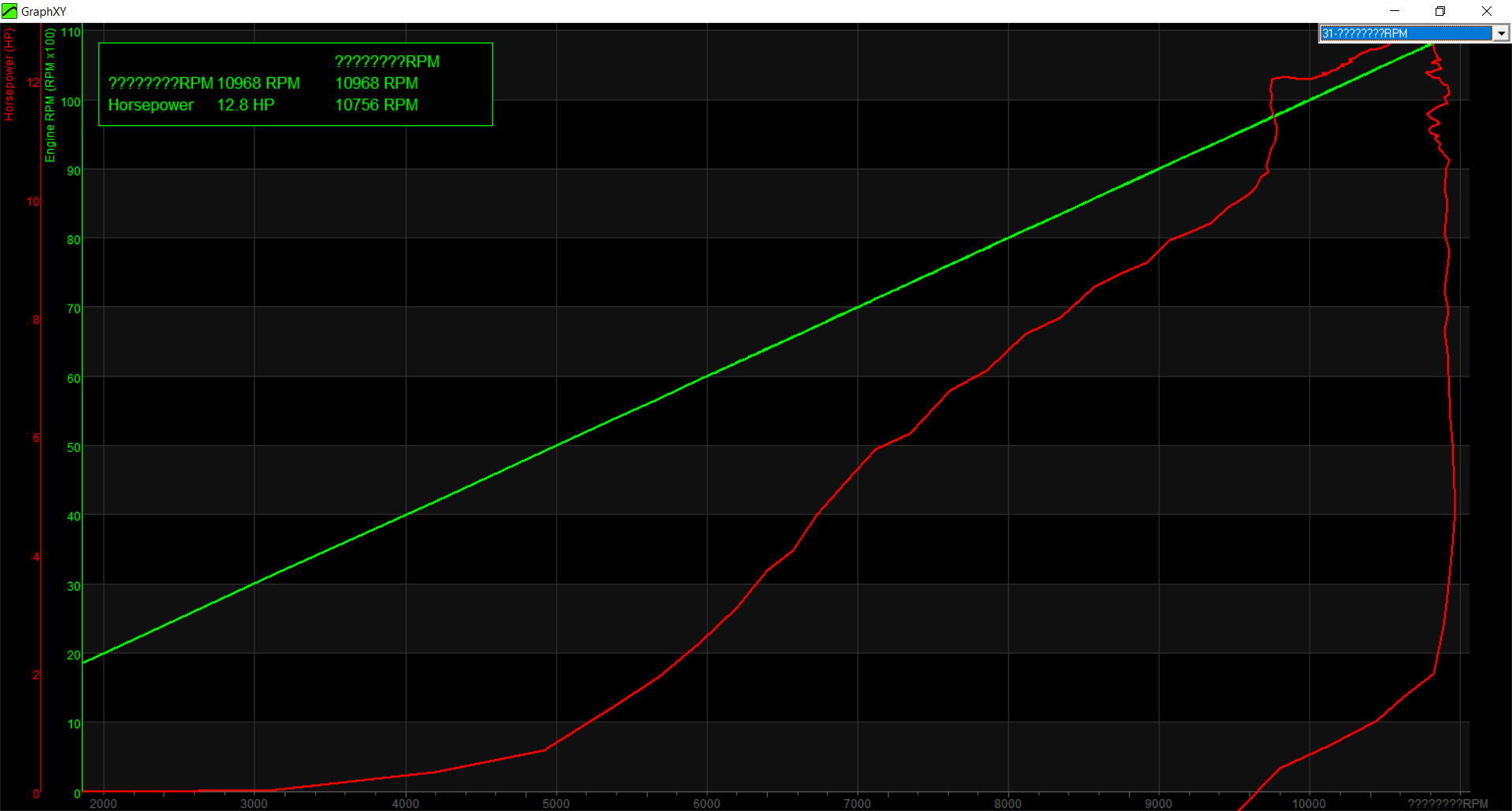
- It is not possible to get the engine HP and the graphs vs actual the RPM (and makes not much sense). As the clutch is centrifugal in most cases the only way to disengage it is LIFTING the wheel and blocking the wheel, but this is a complicated and risky maneouver
- Also, it is not possible to get the actual engine TQ, it is better to use the second method (blocked CVT)
Testing the CVT with the pulley blocked in the “high gear”
This is the method to get the most information from the Engine, almost the same as a vehicle with a manual gearbox (with the limitation of the centrifugal clutch)
- Depending on the type of CVT, the pulley with the rollers may be set in a fixed position using washers, then the CVT will act as a fixed gear (high gear)
- When this modification has been performed, it is necessary to start the engine carefully as the clutch will start the vehicle in the high gear. The recording at full throttle shouldn’t start until the clutch is totally engaged. For instance if the vehicle normally gets the clutch totally engaged at 15 km/h, it is possible that with this modification this happens at 30 km/h
- When a test is recorded in this way, WHP and ETQ (uncorrected) channels are available vs actual Engine RPM, but EHP and corrected TQ are still not available due to the fact that the cetrifugal clutch is quite complex to be disengaged at top speed.
Displaying graphs vs actual Engine RPM
The X-Y graph can be used to display the graphs vs actual RPM (if the Engine RPM channel has enough quality), but in our opinion the resulting graph can be very confusing compared with the graphs-vs-speed, because indeed the purpose of the CVT is to keep the RPM almost constant during the widest (speed) range as possible
Press CTRL+F3 to enter the X-Y graph, and choose the 0x31-Engine RPM for the X axis
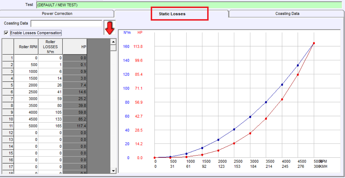
In an inertial dyno RAW power (power observed at rollers) is basically the same as the Wheel power (power that is available at wheels), with the only exception of the power lost at bearings, which can be ignored.
But in a braked dyno using air-cooled eddy current brakes, part of the power is used in the air-pump work in the brake rotors, specially for roller/brake speeds over 2000 RPM.
Solution:
The power wasted by the brake in the air-pump effect could me measured doing a high speed coast down test, but this is a complicated test due to the speeds and power levels involved.
Inertial tests: it is common that the longer the test (higher gear) the more power that the engine can develop, this happens for two reasons:
- Engine Inertia (which is unknown) causes that part of the power is used for accelerating the engine itself. For higher gears the most of the power is used to accelerate the rollers, and as the gear becomes lower the amount of power for accelerating the engine is higher. This maximum happens at first gear (in some engines it could be even about 50%), and of course at Neutral position it is 100%
- If it is a turbocharged engine, the time that the turbo has for reaching its top pressure is lower in lower gears than it higher gears
Braked tests: Both issues are considerably attenuated when performing braked tests of a same duration.
Additionally, In twin roller dynos there is also another source of differences, which is the tyre deformation: normally the lower the gear the higher the pressure that the tyre does against the front roller and the higher the losses, but these losses cannot be measured in the coast down phase. Then my recommendation is using the higher gear possible in these dynos, and even increase the tyre pressure to reduce the deformation (but if you see that slippage increases then you should reach a balance)
example of tyre deformation
Sure!. The general rule for the Low-Pass-Filter (the one that is set in seconds) is that the filter size shouldn’t be bigger than the test duration / 10 (the acceleration part).
As a general rule an inertial dynamometer shouldn’t produce acceleration tests of less than 5 seconds (at the suitable gear), then the minimum filter you should be able to use always is 0.5 s.
For braked dynos as you are able to control the test duration with the brake, our recomendation is having tests between 7 and 10 seconds (or more), then the filter could be 0.7 to 1.0.
On the other hand the filter named “HF” normally is used with fixed values. Actually all filters are low pass type, but the “HF” attenuates specially higher frequencies, (actually it is a Low Pass Filter that focus on higher frequencies), and not so on slow vibrations, for that reason the “Low Pass Filter” was provided to reach lower and lower mechanical frequencies that are present specially in car dynamometers, also the LPF works worse for the very high frequencies, for this reason it is good to use both: “HF” with a fixed value, and LPF depending on the average test size
The recommended values for the “HF” are 5 and 7. The software provides a feedback of the cut frequency, but it is not very intuitive to understand how the test works as frequencies (for instance a “round” HP graph that last 10 seconds has a main componen of a 0.25 Hz wave), for that reason we suggest to use fixed low values (5 to 7)
The problem with the “HF” filter is that the bigger it gets the more delays and distortion it adds, so it is better to use it only for high frequencies (from digital noise and gear teeth irregularities) and not trying to go beyond on filtering, and then using the “LPF” for the mechanical vibrations
In most cases we need to know an estimation of the Power at Engine, which implies to record the coast down phase: friction losses from tyre losses and air-pump losses from brake mainly. This coast down phase must be recorded with the clutch pressed or the Neutral position selected
- Open Gauges Window
- Configure the test:
- Enter data: Vehicle and Customer.
- Mode: Inertial or ramp,
- Starting RPM and ending RPM (for instance 2000 to 6000 RPM), also test duration for ramp test (for instance 10 to 15 sec). Important the ending RPM must be slighly lower than actual value, for instance if the engine reaches 7500 we could set 7000 as top rpm, and the SW will allow us to continue up to 7500 if we want to.
- Stopping mode: normally “Stop When Lower” mode, so the CLUTCH message is shown and the coast down phase is recorded
- Calibrate the ratio: (check the Ratio calibration topic)
- Press “continue” or the start/stop button to enter the semaphore window
- Prepare the vehicle at a speed below the starting RPM
- Open full throttle. If in ramp mode, wait until the pre-load and stabilisation ends
- The test will start automatically
- When ending RPM is reached, the clutch message will be displayed, but the user can continue accelerating if the engine top speed has not been reached
- Press the clutch / Enter Neutral and wait until the recording ends
- The test will stop automatically when speed is below the point set at configuration (by default 50% between starting speed and ending speed)
Important: the software only uses the Roller Channel for all calculations related to the engine (Transformation from Roller Engine scale to Torque at Engine, and Calc RPM for Graph’s Engine RPM axis). This is done in this way for two reasons:
- because some engines cannot always provide Engine RPM readings, for instance diesel engines or engines based on pressured air, or others, and
- because the engine RPM Channel is often a problematic channel, specially in multi-cylinder engines. Only when the Engine RPM channel is read from an ECU the data can be 100% reliable For this reason the software is based on the calibration of Ratio value, which is the relationship between Engine RPM / Roller RPM. For instance if the engine is running at 3000 rpm while the rollers are running at 1000 rpm then the ratio will be 3.0
How to calibrate the ratio:
There are five options:
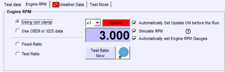
- Using RPM clamp, when using any of the clamps, or in general the Engine RPM TTL input (for instance from the ECU) the software will be updating the ratio value while the vehicle accelerates at the Gauges Window, or also after the first run.
How to use it:
- the user should engage the gear that is going to be used for the test,
- then accelerate progressively and the SW will be updating the ratio value while the acceleration persists,
- then when the ratio value is stable, the ”Update” button can be disabled to block this value, or the mode can be set to Fixed Ratio, so it does not change anymore.
- Then the test can be started as usual either using the start and stop RPM values (this works for inertial and ramp tests).
On the other hand, if the ratio was not calibrated before starting the test, even despite that SW can calculate the correct Ratio value after the test is done, the starting and ending RPM values shouldn’t be used because they will cause random starting and ending points. Alternatives:
-
- Use either manual start/stop (only for inertial)
- Use start and stop referenced to SPEED
- Use OBDII, ECU or XDS data. This method works in the same way that the option 1 (clamp): the SW updates the ratio while the vehicle accelerates at the Gauges window, but the main difference is that the source of Engine RPM value is not the Engine RPM Channel (0x31) but the OBDII/CAN/ECU channel 0x91. The rest of the operation is the same. This external source can be also used at the Manual Calibration Window.
- Fixed Ratio. This is not an actual calibration method, but a mode to keep the latest determined value fixed once it has been determined by other methods
- Manual Ratio Calibration. When there is no way to measure the actual RPM, or the user don’t want to spend time connecting clamps, interfaces or whatever, the SW still is able to find the ratio using the vehicle’s tacho in a visual way. The procedure is simple:
- Open the Ratio Calibration Window (button or CTRL+F7)
- Set a RPM reference. Typically aprox of top rpm /2, for a diesel engine a typical value would be 2000 rpm, and for a petrol engine 3000-4000 rpm depending on the engine
- Accelerate using the gear which will be used for the test until the engine reaches the previously set reference (2000, 3000, 4000…)
- and then click on “Continue” or use the start/stop switch (when it is installed). The software will use the reference and the current roller speed to determine the ratio. For instance reference is 3000 rpm and roller is 1000 rpm, the ratio = 3.0
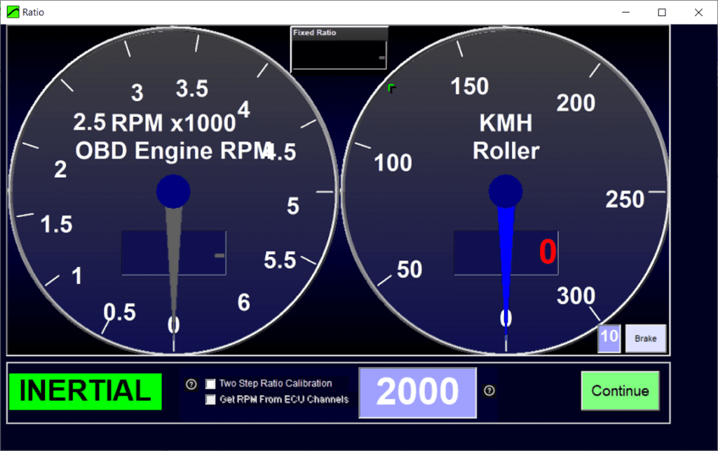
Note that the OBDII/CAN data can be used here too, the main difference is that the user will not need to be so accurate to set the engine to the exact speed that the reference points, because the reference will be updating in real time, thus if the engine is running at 3050 rpm instead of 3000 rpm it will not be important because the reference will be also 3050.
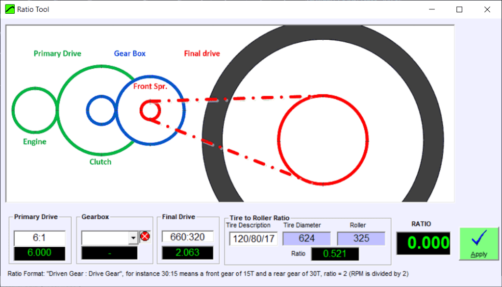
- Ratio manual calculation, based on gearbox and transmission calculations

In the standard version 1.2, only Left and Right buttons are “software” buttons, Then the program can implement several functions (menus, etc) depending on the context, while up, center and down are “hardware/firmware”: the DAQ will perform a fixed function even if the computer is not runing, but that prevents to add more functions depending on the context, specially the menu handling (using the left key all time) is a bit counter intuitive
In the new version 1.3 all buttons are “software” type, then the program can implement several functions depending on the context.
now Up and Dn buttons will perform different functions depending on the mode: Steady rpm up/dn, brake up/dn, etc. But when the menu is visible then will move the current selection up and down, which is more intuitive. Also the left button can be configured in the software for the Cancel function (equivalent to ESC key) or other function like fixed braking (20% or other value) without entering the “Panic” condition. But this is under test now
The idea is that as they are all “software” type they could have more complex functions in the future
Road Simulation is an ADVANCED mode, which is more intended for WLTP cycle, than for testing. Indeed Road Simulation is a kind of modified RAMP which uses a mathematical model to simulate what the vehicle should do in the road according to the instant output the vehicle performs
Users that want to use Road Simulation because they didn’t configure the Ramp correctly will not have a better response with Road Simulation because it is indeed a more complex mode and needs more configuration
Road simulation is easier to be used in rolling road dynos and hub dynos (with automatic gearbox vehicles) than with engine dynos due to the lack of inertia of engine dynos.
Road Simulation is based on three coefficients (C, B, A) to simulate the road and wind-drag load, and a weight value to simulate the inertia of the vehicle.
C is the square term of the polynom and simulates mainly the air force which increases as a square function with speed. Please note that C is not the vehicle’s Cx, but A (frontal surface) by Cx by other constants (see the formula below)
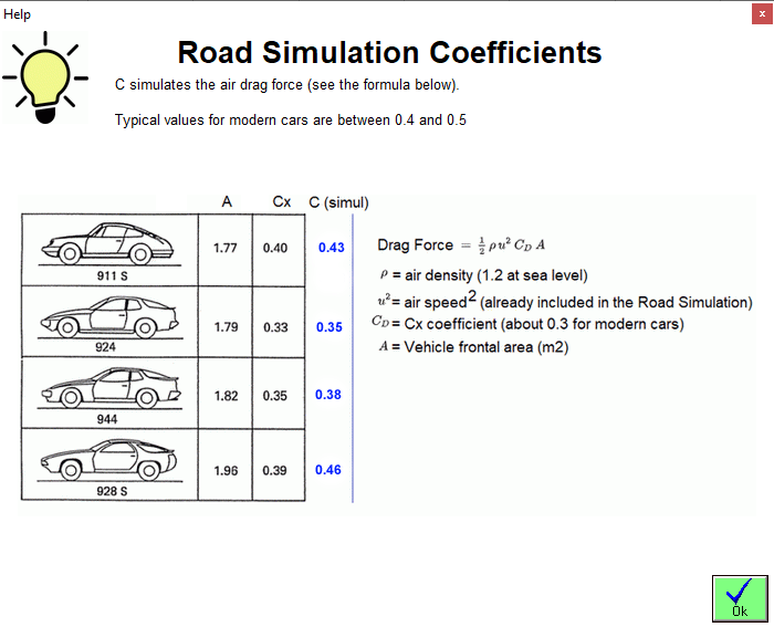
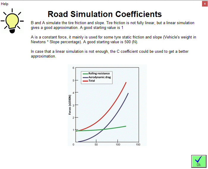
B and A are the linear and constant coefficients in the polynom which mainly simulate the tire friction and slope
Finally the simulated mass is the vehicle’s mass. If the value entered in this field is lower than the equivalent mass of the dyno the simulation will be performed with the dyno equivalent mass, as there is no way (with braked dynos) to accelerate the vehicle to simulate a lower mass (only dynos with electric motors may reach this feature)
It is not a simple task to configure it. You can start with C=0.40, B=1, A=0 and perform several tests. The goal is that the top speed is the same in the dyno as in the road, and that acceleration times are the same. There are advanced procedures to measure those coefficients, but it is not the purpose of this brief explanation.
Additionally there are other coefficients to improve the Road Simulation
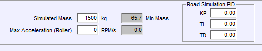
Max acceleration (roller), if it is higher than 0, it limits the maximum acceleration to avoid unexpected behaviour on low inertia dynos
Road Simulation PID: it provides an alternative PID to the main PID used for Steady and Ramp modes, as normally we need a more reactive PID (higher KP, about +50% than the normal KP) in order to provide a better speed tracking in the Road Simulation mode, as the priority is the speed profile, not the power measurement
As alternatives to Ramp and R/S modes (if the PID does not provide the desired results) the user can use the Fixed Brake or Brake Map modes, but they only will work correctly on high inertia dynos (rolling road dynos) as the residual torque (engine torque – brake torque) is very critical on low inertia dynos (hub dynos and engine dynos). In this case only PID modes should be used. A special exception to this case is when testing electric motors in a “reverse test mode” as the motor starts from top speed, then the brake increases its torque progressively until the motor stalls, the motor normally is very stable during all the process regardless the dyno inertia because the motor torque map normally is decreasing with speed, but this does not apply to normal ICE engines because once the TQ peak is reached (say 2000 rpm at a diesel engine) the engine becomes totally unstable and stalls.