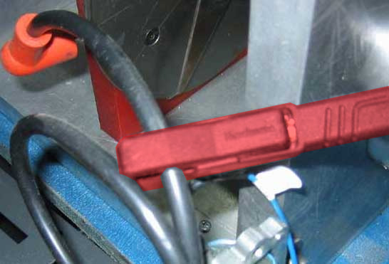
The Capacitive Clamp (Red) (CAP-1) is envisaged to be used mainly on spark cables (High Voltage from coil to the spark). It senses the High Voltage peaks and sends them to the DAQ. In general it is good for single cylinder engines,
Drawbacks: it may get random pulses from other cylinders
There is also a variant (CAP-3) with a blue cable and the 3-pin connector which includes the amplifier circuit in the same clamp, this allows to make the sensing circuit less sensitive and focus only on the near ignition sources, which improves a little its performance on multi cylinder engines. This clamp is provided by default with the SP6 as it only has the 3-pin input
Inductive Clamp (black) (IND-3)
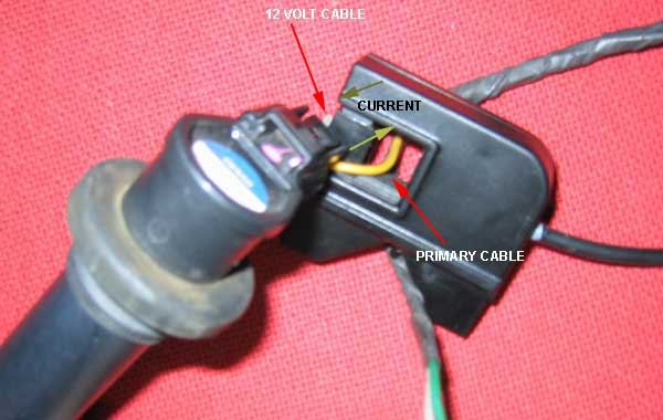
The inductive clamp senses the Current pulses (not voltage) and it is provided mainly to sense the current at ONE of the wires that go to the coil, specially for over-spark coils (as there is no spark cable!).
- In motorcycles typically there are two cables going to the coil, please set the clamp at ONE of the cables. Note that the clamp is sensitive to one direction but less to the other.
- In cars typically we have three cables going to the “amplified coil”, one of the cables is GND, the other is 12V and the other is the low power activation. As it is the coil who amplifies the signal and creates the current pulses, only the GND and 12V cables will have a pulses of current (use the clamp on ONE of them). The signal cable could even have almost Zero current, as normally these coils use an IGBT (its conductivity based on gate’s voltage, not current)
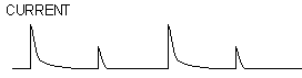
Current model:

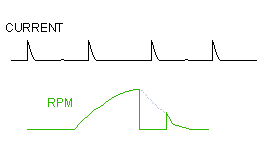
Drawbacks: mnany engines work in a “wasted-spark” schema to simplify the timing (one spark per turn). This means that they do one spark at compression-combustion stroke, but also a spark in exhaust stroke. This spark at exhaust stroke has no impact over the engine performance, but as the pressure is lower than during the combustion the sparks tend to be weaker (it is necessary less voltage to jump the spark gap than when working at a high pressure). This causes that the pulses sensed at the clamp are alternatively high and low, high and low, but also not at a constant level, but the weak pulse may sometimes overpass the activation level, and other times may not. Which will lead to show alternatively the value “RPM”, and “RPM / 2” in the gauges and the graphs
And when the engine decelerates as the amount of air-fuel mixture is very low in the chamber, even the compression phase may show 0 RPM as in the graph below, although this normally happens during a short time as the engine reaches the idling speed quite fast (Neutral Gear or Clutch have to be active to do the coast down test)