Important: the software only uses the Roller Channel for all calculations related to the engine (Transformation from Roller Engine scale to Torque at Engine, and Calc RPM for Graph’s Engine RPM axis). This is done in this way for two reasons:
- because some engines cannot always provide Engine RPM readings, for instance diesel engines or engines based on pressured air, or others, and
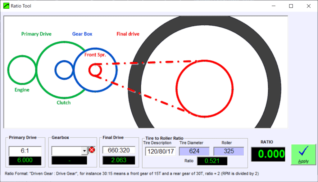
- because the engine RPM Channel is often a problematic channel, specially in multi-cylinder engines. Only when the Engine RPM channel is read from an ECU the data can be 100% reliable For this reason the software is based on the calibration of Ratio value, which is the relationship between Engine RPM / Roller RPM. For instance if the engine is running at 3000 rpm while the rollers are running at 1000 rpm then the ratio will be 3.0
How to calibrate the ratio:
There are five options:
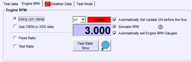
- Using RPM clamp, when using any of the clamps, or in general the Engine RPM TTL input (for instance from the ECU) the software will be updating the ratio value while the vehicle accelerates at the Gauges Window, or also after the first run.
How to use it:
- the user should engage the gear that is going to be used for the test,
- then accelerate progressively and the SW will be updating the ratio value while the acceleration persists,
- then when the ratio value is stable, the ”Update” button can be disabled to block this value, or the mode can be set to Fixed Ratio, so it does not change anymore.
- Then the test can be started as usual either using the start and stop RPM values (this works for inertial and ramp tests).
On the other hand, if the ratio was not calibrated before starting the test, even despite that SW can calculate the correct Ratio value after the test is done, the starting and ending RPM values shouldn’t be used because they will cause random starting and ending points. Alternatives:
-
- Use either manual start/stop (only for inertial)
- Use start and stop referenced to SPEED
- Use OBDII, ECU or XDS data. This method works in the same way that the option 1 (clamp): the SW updates the ratio while the vehicle accelerates at the Gauges window, but the main difference is that the source of Engine RPM value is not the Engine RPM Channel (0x31) but the OBDII/CAN/ECU channel 0x91. The rest of the operation is the same. This external source can be also used at the Manual Calibration Window.
- Fixed Ratio. This is not an actual calibration method, but a mode to keep the latest determined value fixed once it has been determined by other methods
- Manual Ratio Calibration. When there is no way to measure the actual RPM, or the user don’t want to spend time connecting clamps, interfaces or whatever, the SW still is able to find the ratio using the vehicle’s tacho in a visual way. The procedure is simple:
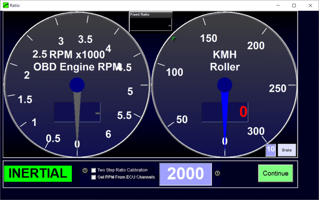
- Open the Ratio Calibration Window (button or CTRL+F7)
- Set a RPM reference. Typically aprox of top rpm /2, for a diesel engine a typical value would be 2000 rpm, and for a petrol engine 3000-4000 rpm depending on the engine
- Accelerate using the gear which will be used for the test until the engine reaches the previously set reference (2000, 3000, 4000…)
- and then click on “Continue” or use the start/stop switch (when it is installed). The software will use the reference and the current roller speed to determine the ratio. For instance reference is 3000 rpm and roller is 1000 rpm, the ratio = 3.0
Note that the OBDII/CAN data can be used here too, the main difference is that the user will not need to be so accurate to set the engine to the exact speed that the reference points, because the reference will be updating in real time, thus if the engine is running at 3050 rpm instead of 3000 rpm it will not be important because the reference will be also 3050.
- Ratio manual calculation, based on gearbox and transmission calculations