ShockAbsorber Machine

What does the machine include:

  • Machine Frame.
  • Machine Size: 0.5 W, 0.7 L, 1.63 H (meters)
  • Weight: 120 kg
  • Vertical bars: 1.5 meter total, 1.2 m usable
  • 4KW (5.5 HP) motor
  • Reduction grarbox. 250 RPM nominal, max 460 RPM
  • VFD: Variable Frequency Drive 380V 4KW (230V optional)
  • max stroke: 100 mm
  • 1000 kg Load Cell
  • 100 mm Linear Potentiometer
  • ShockAnalyzer DAQ
  • FTDI USB to RS232 adapter
  • Standard Shock Mounting (rear shock type)

Manual (EN): Shock Analyzer Dynamometer v2.1-Eng

Manual (FR): Shock Analyzer Dynamometer v2.1-Fr

*Prices do not include VAT

Specifications

Electric Motor

Shockabsorber dynamometers are usually powered by 3-phase AC induction electric motors. The motors size and power is limited to its supply voltage. It is strongly recommended to drive the motor with a VFD to be able to perform the automated multi-speed tests. For power values under 4 HP, the VFD can be powered from a single phase grid. But for higher power values, normally 3-phase grid is necessary.

Reduction Gearbox

Output from the motor is geared down with a reduction box. The maximum output shaft speed should be in the 300 to 500 RPM range.
Note that although most induction motors work at 1450 RPM at 50 Hz, the VFD can easilly increase this speed up to almost twice (100 Hz), which results in a high torque at low RPM (for 300 RPM reduction box), and increased speed to allow testing the shockabsorber at higher speeds with a small reduction in total power.

Load Cell

A load cell is a transducer that converts force on it into analog electrical signals. A load cell attached to the crossbeam will measure the force placed on the shock.

Shock temperature sensor

Shock temperature is measured using a thermocouple attached to the casing of the shock with a Velcro strap. Shock performance can vary dramatically at different temperatures. With the temperature monitoring system, you can determine how your shock will proform under various temperatures. You can warm the shock directly on dynamemeter (thermocouple is not included in the kit).

Potentiometer

Shockanalyzer DAQ uses a 100 mm potentiometer to meassure speed and position, this part is supplied with the kit. There is an optional 150 mm potentiometer.


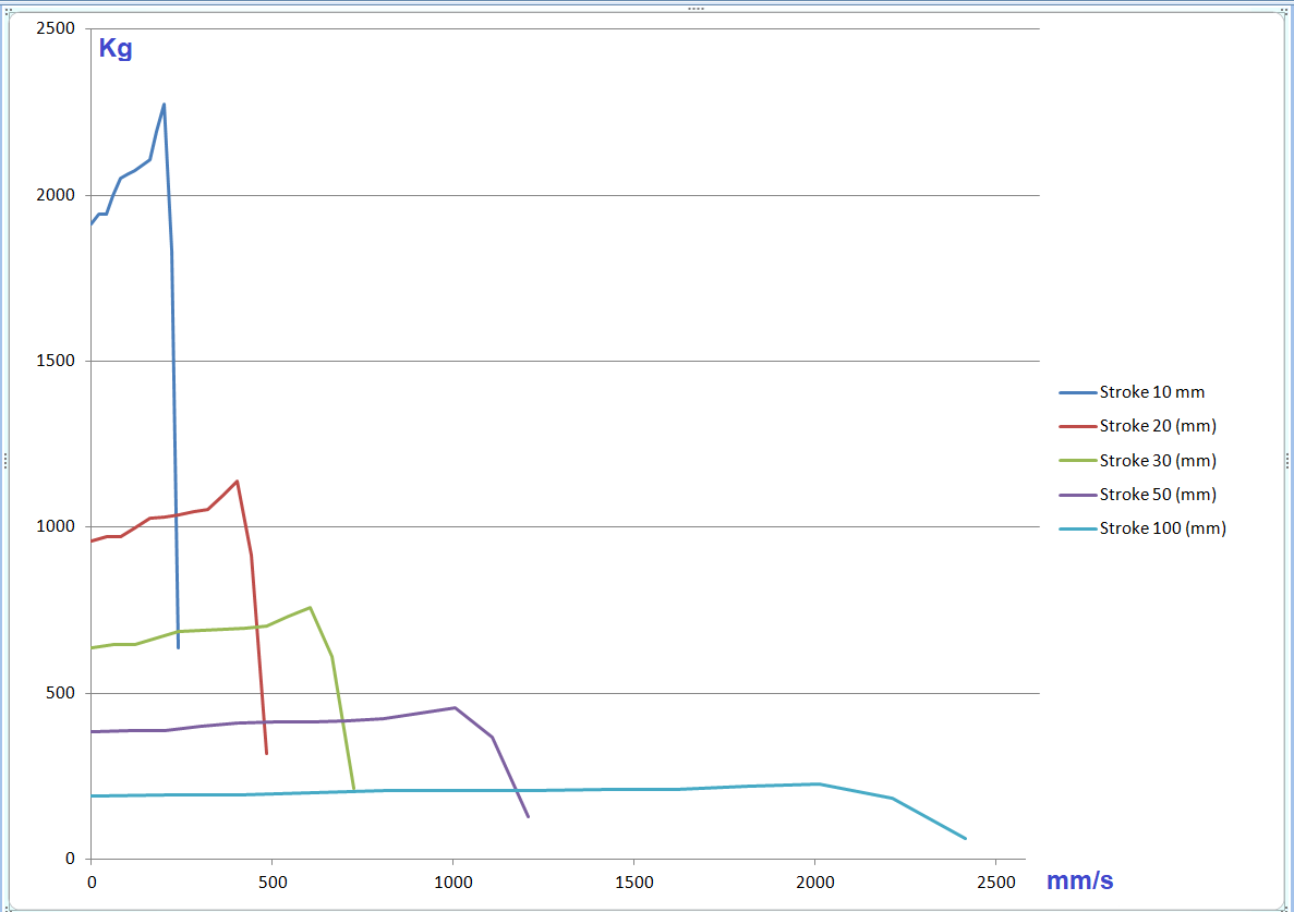
Force vs Speed at different Strokes

Stroke length Selector Drum

There are ten screewed holes located over spiral shape, connecting rod can be fixed in any hole to select stroke length. The longer the stoke, the greather the power needed on motor to move the shock absorber. At higher stroke, it is possible that the motor couldn’t move the shock absorber, thus we recomed to start at position 1 and increase it step by step (this part is not included with the electronic kit)

Position Stroke length
1 10 mm
2 20 mm
3 30 mm
4 40 mm
5 50 mm
6 60 mm
7 70 mm
8 80 mm
9 90 mm
10 100 mm

Mechanism

Piston – Crank Mechanism

This mechanism consists of a drum (crank), connecting rod, and piston similar to the piston-crank mechanism in an internal combustion engine. The drum has holes drilled to achieve different stroke lengths. The disadvantage of using this mechanism is that it does not produce perfect sinusoidal motion in the piston, but having a longer connecting rod can compensate for this. Although it is not necessary to have sinusoidal motion, it does help reduce vibration. The advantage to this mechanism is its cost effectiveness because there is less high tolerance machining.

Scotch Yoke Slider (NOT AVAILABLE)

The scotch yoke has one advantage over the piston-crank mechanism. It produces perfectly sinusoidal motion. The scotch yoke has two major disadvantages. It is expensive. The fine tolerance that would be required for the slider would increase machining costs. There is also more maintenance required with a slider joint.

How is it used?

Preparation:

  • Shockabsorber is bolted into the dyno unit on the provided mounting locations
  • The stroke is selected physically on the rotary drum
  • If stroke was changed, the velocity has to be calibrated for the new stroke value
  • Test table is filled with the required speeds and number of turns for stabilisation and recording

Test:

  • “Spring” test is performed to record the initial force offset and force vs position coefficient (similar effect like a spring, but caused by the gas)
  • Test is started and motor speed is driven by the VFD to the values specified in the test table.
  • Shockanalyzer DAQ transmits all postion, force and temperature values, and those are recorded in the computer
  • The computer displays the data in several graphical modes (force vs position, force vs speed, force vs peak speed, etc)